Solar Tools Kit with 393 FC Clamp Meter, Irradiance Meter and Solar Test Leads


Key features
- Measure safely with CAT III 1500 V rated clamp meter
- Thin jaw for access to cables in crowded combiner boxes
- Work efficiently with dc power measurement, audio polarity and visual continuity
- Measure solar irradiance, ambient and PV module temperature, array orientation and tilt angles
- Solar PV test lead sets are designed for use with solar clamp meters that accept 4mm banana plugs, rated to CAT III 1000 V / CAT IV 600 V


Sale ends soon.
Shop now!
Product overview: Solar Tools Kit with 393 FC Clamp Meter, Irradiance Meter and Solar Test Leads
The 393 FC CAT III 1500 V True-rms Clamp Meter with iFlex is an industrial clamp meter designed for solar photovoltaic (PV) installation technicians and maintenance professionals who work in high voltage dc environments. Safely connect the Solar PV test leads to the clamp meter to validate voltage and current from individual panels or a series of panels in a PV array. The inline capabilities of the Solar PV PVLEAD3 leads allow the system to remain online and generating power while testing without needing to pierce the line. Use the IRR1-SOL to obtain the amount of solar irradiance necessary to calculate the IV curve of the power output. Validate that the panel or string of panels are outputting the correct voltage.
Key functions of the solar clamp meter, irradiance meter and Solar PV test leads:
- View voltage and current simultaneously with the meter's dual display
- IP54 rated meter, ideal for work outdoors including PV panel testing
- DC power measurement, showing readings in kVA
- Logging and reporting of test results via Fluke Connect software
- Make instantaneous measurements to determine the watts per square meter solar irradiation, required by IEC 62446-1 standard
- Solar PV leads comply to IEC / EN 61010-031
What's in the box:
- Fluke 393 FC CAT III 1500 V TRMS clamp meter
- Test leads, CAT III 1500 V rated, right angle plugs, with safety caps
- iFlex 18 inch flexible current probe
- TPAK magnetic hanging strap
- Premium carrying case
- 3-year warranty
- FLK-IRR1-SOL Solar Irradiance Meter
- FLK80PR-IRR External Temperature Probe with Suction Cup
- C250 Carrying Case with Shoulder Strap
- (4) AA Alkaline Batteries (installed)
- User Manual
- Pomona PVLEAD1 Solar PV Connector to 4 mm Test Lead Set
- Pomona PVLEAD3 Solar PV Clamp Test Lead Set
Specifications: Solar Tools Kit with 393 FC Clamp Meter, Irradiance Meter and Solar Test Leads
Specifications: Fluke 393 FC CAT III 1500 V True-rms Solar Clamp Meter
| General | |||
| Maximum voltage between any Terminal and Earth Ground | |||
| AC | 1000 V | ||
| DC | 1500 V | ||
| Batteries | 2 AA IEC LR6 alkaline | ||
| Display | Dual display with backlight | ||
| Automatic Power Off | 20 minutes | ||
| Electrical | |||
| Accuracy | |||
| Accuracy is specified for 1 year after calibration, at operating temperatures of 18 °C to 28 °C, relative humidity at 0 % to 75 %. Accuracy specifications take the form of: ±([% of Reading] + [Number of Least Significant Digits]). | |||
| Temperature Coefficients | Add 0.1 x specified accuracy for each °C > 28 °C or < 18 °C | ||
| AC Current: Jaw | |||
| Range | 999.9 A | ||
| Resolution | 0.1 A | ||
| Accuracy | 2 % + 5 digits (10 Hz to 100 Hz) | ||
| 2.5 % + 5 digits (100 Hz to 500 Hz) | |||
| Crest Factor (50/60 Hz) | 2.5 @600.0 A | ||
| 3.0 @500.0 A | |||
| 1.42 @999.9 A | |||
| Add 2 % for C.F. >2 | |||
| AC Current: Flexible Current Probe | |||
| Range | 999.9 A | ||
| 2500 A | |||
| Resolution | 0.1 A (≤999.9 A) | ||
| 1 A (≤2500 A) | |||
| Accuracy | 3 % RD + 5 digits (10 Hz to 500 Hz) | ||
| Crest Factor (50/60Hz) | 2.5 @1400 A | ||
| 3.0 @1100 A | |||
| 1.42@2500 A | |||
| Add 2 % for C.F. >2 | |||
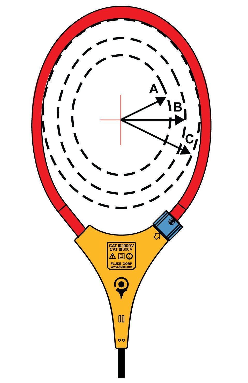
| Position Sensitivity | |||
 |
|||
| Distance from Optimum | i2500-10 Flex | i2500-18 Flex | Error |
| A | 12.7 mm (0.5 in) | 35.6 mm (1.4 in) | ±0.5 % |
| B | 20.3 mm (0.8 in) | 50.8 mm (2.0 in) | ±1.0 % |
| C | 35.6 mm (1.4 in) | 63.5 mm (2.5 in) | ±2.0 % |
| Measurement uncertainty assumes centralized primary conductor at optimum position, no external electrical or magnetic field, and within operating temperature range. | |||
| DC Current | |||
| Range | 999.9 A | ||
| Resolution | 0.1 A | ||
| Accuracy | 2 % RD + 5 digits[1] | ||
| [1] When using the ZERO (B) function to compensate for offsets. | |||
| AC Voltage | |||
| Range | 600.0 V | ||
| 1000 V | |||
| Resolution | 0.1 V (≤600.0 V) | ||
| 1 V (≤1000 V) | |||
| Accuracy | 1 % RD + 5 digits (20 Hz to 500 Hz) | ||
| DC Voltage | |||
| Range | 600.0 V | ||
| 1500 V | |||
| Resolution | 0.1 V (≤600.0 V) | ||
| 1 V (≤1500 V) | |||
| Accuracy | 1 % RD + 5 digits | ||
| mV dc | |||
| Range | 500.0 mV | ||
| Resolution | 0.1 mV | ||
| Accuracy | 1 % RD + 5 digits | ||
| Amps Frequency: Jaw | |||
| Range | 5.0 Hz to 500.0 Hz | ||
| Resolution | 0.1 Hz | ||
| Accuracy | 0.5 % RD + 5 digits | ||
| Trigger Level | 5 Hz to 10 Hz, ≥10 A | ||
| 10 Hz to 100 Hz, ≥5 A | |||
| 100 Hz to 500 Hz, ≥10 A | |||
| Amps Frequency: Flexible Current Probe | |||
| Range | 5.0 Hz to 500.0 Hz | ||
| Resolution | 0.1 Hz | ||
| Accuracy | 0.5 % RD + 5 digits | ||
| Trigger Level | 5 Hz to 20 Hz, ≥25 A | ||
| 20 Hz to 100 Hz, ≥20 A | |||
| 100 Hz to 500 Hz, ≥25 A | |||
| Voltage Frequency | |||
| Range | 5.0 Hz to 500.0 Hz | ||
| Resolution | 0.1 Hz | ||
| Accuracy | 0.5 % RD + 5 digits | ||
| Trigger Level | 5 Hz to 20 Hz, ≥5 V | ||
| 20 Hz to 100 Hz, ≥5 V | |||
| 100 Hz to 500 Hz, ≥10 V | |||
| DC Power | |||
| Range | 600.0 kVA (600.0 V dc range) | ||
| 1500 kVA (1500 V dc range) | |||
| Resolution | 0.1 kVA | ||
| 1 kVA | |||
| Accuracy | 2 % RD + 2.0 kVA | ||
| 2 % RD + 20 kVA | |||
| Resistance | |||
| Range | 600.0 Ω | ||
| 6000 Ω | |||
| 60.00 kΩ | |||
| Resolution | 0.1 Ω (≤600.0 Ω) | ||
| 1 Ω (≤6000 Ω) | |||
| 0.01 kΩ (≤60.00 kΩ) | |||
| Accuracy | 1 % RD + 5 digits | ||
| Capacitance | |||
| Range | 100.0 μF | ||
| 1000 μF | |||
| Resolution | 0.1 μF (≤100.0 μF) | ||
| 1 μF (≤1000 μF) | |||
| Accuracy | 1 % RD + 5 digits | ||
| Inrush Trigger Level | 5 A | ||
| Mechanical | |||
| Size (L x W x H) | 281 mm x 84 mm x 49 mm | ||
| Weight (with batteries) | 520 g | ||
| Jaw Opening | 34 mm | ||
| Flexible Current Probe Diameter | 7.5 mm | ||
| Flexible Current Probe Cable Length | |||
| (head to electronics connector) | 1.8 m | ||
| Environmental | |||
| Operating Temperature | -10 °C to 50 °C | ||
| Storage Temperature | -40 °C to 60 °C | ||
| Operating Humidity | Non condensing (<10°C) | ||
| ≤90 % RH (at 10 °C to 30 °C) | |||
| ≤75 % RH (at 30 °C to 40 °C) | |||
| ≤45 % RH (at 40 °C to 50 °C) | |||
| Operating Altitude | 2000 m | ||
| Storage Altitude | 12 000 m | ||
| Ingress Protection (IP) Rating | IEC 60529: IP54 non-operating | ||
| Electromagnetic Compatibility (EMC) | |||
| International | IEC 61326-1: Portable, Electromagnetic Environment, IEC 61326-2-2 CISPR 11: Group 1, Class A | ||
| Group 1: Equipment has intentionally generated and/or uses conductively-coupled radio frequency energy that is necessary for the internal function of the equipment itself. | |||
| Class A: Equipment is suitable for use in all establishments other than domestic and those directly connected to a low-voltage power supply network that supplies buildings used for domestic purposes. There may be potential difficulties in ensuring electromagnetic compatibility in other environments due to conducted and radiated disturbances. | |||
| Caution: This equipment is not intended for use in residential environments and may not provide adequate protection to radio reception in such environments. | |||
| USA (FCC) | 47 CFR 15 subpart B. This product is considered an exempt device per clause 15.103. | ||
| Safety | |||
| General | IEC 61010-1, Pollution Degree 2 | ||
| Measurement | IEC 61010-2-032: CAT III 1500 V / CAT IV 600 V | ||
| IEC 61010-2-033: CAT III 1500 V / CAT IV 600 V | |||
| Wireless Radio | |||
| Radio frequency certification | FCC ID: T68-FBLE, IC: 6627A-FBLE | ||
| Wireless Radio Frequency Range | 2400 MHz to 2483.5 MHz | ||
| Output Power | <100 mW | ||
| SIMPLIFIED EU DECLARATION OF CONFORMITY | |||
| Hereby, Fluke declares that the radio equipment contained in this Product is in compliance with Directive 2014/53/EU. | |||
| The full text of the EU declaration is available at the following Internet address: | |||
| www.fluke.com/en-us/declaration-of-conformity | |||
Specifications: Fluke Solar Irradiance Meter
| Irradiance | |
| Measuring Range | 0 to 1400 W/m² |
| Resolution | 1 W/m² |
| Measuring Accuracy | ± (5 % + 5 Digit) |
| Temperature Measurement | |
| Measuring range (°C) | -30 °C to 100 °C (-22 °F to 212 °F) |
| Resolution | 0.1 °C (0.2 °F) / 1 °F @>100 °F |
| Measuring Accuracy | ±1 °C (±2 °F) @ -10 °C to 75 °C (14 °F to 167 °F), ±2 °C (±4 °F) @ -30 °C to -10 °C (-22 °F to 14 °F) and 75 °C to 100 °C (167 °F to 212 °F) |
| Note: Temperature measurement response time: ~30 sec. | |
| Inclination Angle | |
| Measuring Range | -90° to +90° |
| Resolution | 0.1° |
| Measuring Accuracy | ± 1.5°@ -50° to +50°, ±2.5° @ -85° to -50° and +50° to +85°, ±3.5° @ -90° to -85° and +85° to +90° |
| Compass | |
| Measuring Range | 0° to 360° |
| Resolution | 1° |
| Measuring Accuracy | ±7° |
| Note: a) Measurements valid for device inclination between -20° and +20° to horizontal. Outside that range on LCD will be shown "---". b) Result is referred to magnetic north. |
|
| Temperature | |
| Operating Temperature IRR1-SOL | -20 °C to 50 °C (humidity <80%), noncondensing |
| Operating Temperature 80PR-IRR | -30 °C to +100 °C |
| Storage Temperature | -30 °C to 60 °C (humidity <80%) |
| Altitude | 0 m to max. 2000 m |
| Electromagnetic Compatibility (EMC) | |
| International | IEC 61326-1: Portable Electromagnetic Environment |
| CISPR 11: Group 1, Class A | |
| Group 1: Equipment has intentionally generated and/or uses conductively-coupled radio frequency energy that is necessary for radio frequency energy that is necessary for the internal function of the equipment itself. Class A: Equipment is suitable for use in all establishments other than domestic and those directly connected to a low voltage power supply network that supplies buildings used for domestic purposes. There may be potential difficulties in ensuring electromagnetic compatibility in other environments due to conducted and radiated disturbances. | |
| Caution: This equipment is not intended for use in residential environments and may not provide adequate protection to radio reception in such environments. | |
| USA (FCC) | 47 CFR 15 subpart B. This product is considered an exempt device per clause 15.103. |
| Protection | |
| IP Protection | IP40 |
| Power Supply & Battery Life | |
| Batteries | 4 AA Alkaline Batteries |
| Battery Life (typical) | 50 hours (≤9000 readings) |
| Auto Power Off | 30 minutes |
| Dimensions | |
| L x W x H | 150 x 80 x 35 mm (5.90 x 3.14 x 1.37 in) |
| Weight | 231 g (0.5 lb) |
Specifications: Pomona PVLEAD1 and PVLEAD3 MC4 Solar Clamp Test Lead Set
| PVLEAD1 | PVLEAD3 | |
| MC4 to 4mm Test Lead Set | MC4 Solar Clamp Meter Test Lead Set | |
| Contact | Brass, Nickel Plated | Brass, Nickel Plated |
| Length | 60” | 36”, 12” |
| Voltage | CAT III 1000V, | CAT III 1000V, |
| CAT IV 600V | CAT IV 600V | |
| Current | 20 amp | 20 amp |
| Standards | IEC 61010-031 | IEC 61010-031 |