PVA-1500HE2 I-V Curve Tracer, Insulation, Clamp and Multimeter Kit


Key Features
- Measures and displays I-V curves up to 1500V and 30A, including on high efficiency modules
- Wireless interfaces for faster setup, safer work environment, and freedom of movement during PV troubleshooting
- Automates data management, analysis, and reporting
- Validate voltage and current from individual panels or a series of panels in a PV array
- Verify cable integrity with insulation resistance testing
Product overview: PVA-1500HE2 I-V Curve Tracer, Insulation, Clamp and Multimeter Kit
Training
Fluke offers a variety of training related to PV test and measurement. Training can either be delivered as a virtual on-demand course or as a live online presentation/discussion format with a product expert (may differ regionally).
This toolkit combines the precision of the PVA-1500HE2 I-V Curve Tracer, the versatility of the Fluke 393 FC Solar Clamp Meter, the reliability of the Fluke 87V Digital Multimeter, and the advanced capabilities of the Fluke 1587 FC Insulation Multimeter. The PVA-1500HE2 offers an array of advanced features, including high throughput I-V curve tracing, providing quick and detailed performance data. Its intuitive user interface enables easy navigation and real-time analysis, allowing for immediate identification of potential issues. The 393 FC Solar Clamp Meter enables precise measurement of DC current and voltage, essential for performance testing and troubleshooting of solar panels and inverters. The 87V Digital Multimeter provides reliable measurements of AC/DC voltage, current, resistance, and capacitance, facilitating system integrity verification and electrical fault diagnosis. Additionally, the 1587 FC Insulation Multimeter offers insulation resistance testing, helping to identify potential safety hazards and prevent system failures. From commissioning and routine maintenance to troubleshooting and performance optimization, this toolkit empowers solar professionals to ensure the efficiency, reliability, and safety of solar installations with confidence.
The 393 FC is a CAT III 1500 V True-RMS Clamp Meter is designed for solar photovoltaic (PV) installation technicians and maintenance professionals who work in high voltage DC environments. Solar site electrical testing and troubleshooting with the 393 FC includes:
- Measuring current and voltage
- Conducting continuity and resistance tests
- Performing inverter efficiency tests
- Diagnosing problems like short circuits
- Conducting preventive maintenance to identify and address potential issues early
The 87V Industrial Multimeter is the ideal electrical troubleshooting solution for solar inverters, combiner boxes and battery storage systems. Solar site electrical testing and troubleshooting with the 87V includes:
- Measuring current and voltage
- Identifying issues with connections and components with continuity and resistance tests
- Identifying faulty diodes impacting system performance
- Testing capacitors in inverters and power equipment
- Monitoring component temperatures for safety
- Diagnosing problems like short circuits
- Conducting preventive maintenance to identify and address potential issues early
In addition to the 87V capabilities, the 1587 FC Insulation Multimeter combines a digital multimeter with an insulation tester, allowing for insulation resistance testing crucial for cable and component integrity.
Measure your solar PV system performance
The PVA-1500HE2 is a cutting-edge I-V curve tracer kit designed to measure PV system performance. With this high precision testing equipment, you can reliably assess the health and performance of solar modules and arrays, making informed decisions to enhance their output and longevity.
The PVA-1500HE2 kit offers an array of advanced features, including high throughput I-V curve tracing, providing quick and detailed performance data. Its intuitive user interface enables easy navigation and real-time analysis, allowing for immediate identification of potential issues. By pinpointing problems early, you can maximize your solar energy production and minimize downtime.
Comprehensive measurements and efficient analysis
For commissioning, operations, maintenance, and troubleshooting of PV arrays, I-V curve testing is the most complete solar module performance measurement. Quick analysis of curve datasets aids in detecting outliers, and the stored data functions as a baseline for future performance inquiries.
Accurate I-V curve tracing
The PVA measures the I-V (current versus voltage) curve of a PV string or module using a capacitive load. The measurement is typically performed at the string level by connecting directly to the string or at a combiner box using the fuses to select the string under test. The number of I-V curve points can be selected at 100 or 500. Additionally, the PVA generates the P-V (power versus voltage) curve, Isc, Voc, Imp, Vmp, Pmax, fill factor, and performance factor (the ratio of measured to expected maximum power).
Time-saving interface
With a tablet or laptop (Windows only) as the user interface, perform more tests per hour and display the data in multiple, easy to read formats. Save your measurements by touching your customized array tree at the branch you are measuring. The software automatically calculates the expected I-V curve and displays the performance factor.
Advanced High Efficiency PV Testing Capabilities
Accurate measurement of high efficiency modules up to 30A: Highly efficient modules (>19% module efficiency) possess high
capacitance, posing a challenge for some I-V curve tracers that may not be able to measure them. The PVA-1500HE2 is uniquely
designed to measure all string types, even those with high efficiency modules, up to 30A.
Rapid performance in high temperature environments: The PVA-1500HE2 operates with a swift sweep-to-sweep delay of 9 seconds (at Voc<1350V). This results in the ability to measure 3.5 MW within an hour, even in high-temperature settings where standard curve tracers often fail due to overheating.
SolSensor™ Wireless PV Reference Sensor
The SolSensor™ provides irradiance, module temperature, and array tilt data to the PV model. The model uses this information to predict the I-V curve shape at these operating conditions and to translate the measured curve to standard test conditions. The SolSensor™ clamps to the module frame, automatically orienting the irradiance sensor to the plane-of-array.
The spectral response of the silicon photodiode sensor in the SolSensor™ is corrected for the PV technology under test. Special
factors are provided for multi- and mono-crystalline cells as well as cadmium telluride (CdTe) and other thin film technologies. The
sensor is temperature compensated and the angular response of each unit is calibrated for rotation and elevation. As a result, the SolSensor™ is accurate over a broad range of technologies, sky conditions, and sun angles, allowing I-V curve measurements earlier and later in the day.
The SolSensor™ provides two external thermocouple inputs for measuring module backside temperatures. Effective cell temperature can also be calculated directly from the measured I-V curve per IEC 60904-5. The PVA’s SmartTemp™ feature, optionally, blends these two methods for best accuracy.
The PVA and SolSensor™ communicate wirelessly with your PC via WiFi with a line-of-sight wireless range of 100m. That means no wires underfoot, quick setup, the ability to move around while troubleshooting strings, and flexibility to measure multiple combiner boxes with a single SolSensor™ setup.
Turn PVA data into key insights, visualizations, and customizable reports
Capture data in the field with the PVA Application and validate the results with the Data Analysis Tool (DAT), a Microsoft Excel™-based solution streamlining the analysis of PVA I-V curve data. It presents analysis results in multiple formats. It compiles key PV parameters in a string table, flags non-conforming strings, and delivers a statistical overview of the entire array. Additionally, it visually combines string I-V curves at the combiner box level, offering a clear depiction of consistency and identifying atypical strings. The tool also generates histograms for PV parameters across the string population, and this data can be added to a customizable report exported as a PDF. The Data Analysis Tool (DAT) can be downloaded for free use with any PVA.
Supported languages: English, French, Spanish, German, Italian, Traditional Chinese, Simplified Chinese, and Brazilian Portuguese.
What's in the box:
PVA-1500HE2:- PVA-1500 V unit
- SolSensor™ and clamp
- Alligator test leads
- MC4 disconnect tool
- Chargers
- 2x thermocouples and adhesive disks
- Sensor cleaning supplies
- Transit case (included with the PVA-1500HE2)
- Available by free download: PVA Application and Data Analysis Tool
393 FC:
- 393 FC CAT III 1500 V TRMS clamp meter
- Test leads, CAT III 1500 V rated, right angle plugs, with safety caps
- iFlex 18 inch flexible current probe
- TPAK magnetic hanging strap
- Premium carrying case
87V:
- 87V Industrial Multimeter
- TL75 Test Leads (TL175 Eur)
- AC175 Alligator Clips
- Holster with tilt-leg, test lead storage
- 80BK Temperature Probe
- 9V Battery (Installed)
1587 FC:
- 1587 FC Insulation Multimeter
- Remote probe
- Test leads
- Alligator clips
- K-type thermocouple
- Soft case
Specifications: PVA-1500HE2 I-V Curve Tracer, Insulation, Clamp and Multimeter Kit
| PVA-1500 Specifications | ||
| PVA-1500T2 | PVA-1500HE2 | |
| Voltage Range (Voc) | 20 to 1500V DC | |
| Maximum Current Range (Isc) | ||
| Module Efficiency <19% | 0 to 30A DC | |
| Module Efficiency ≥19% | 0 to 10A DC | 0 to 30A DC |
| Voltage Accuracy (0 °C to 45 °C) | ±(0.5% ±0.25V) | |
| Current Accuracy (0 °C to 45 °C) | ±(0.5% ±0.04A) | |
| Power Accuracy (0 °C to 45 °C) | ±(1.7 % + 1.0 W) (current ≥3 A, module efficiency <19 %) | |
| Voltage Resolution | 25 mV | |
| Current Resolution | 2 mA | |
| Measurement Throughput | ||
| Sweep-to-sweep delay (@VOC ≤ 1350V) | <9 seconds | |
| Max number of I-V sweeps per hour (@VOC ≤ 1350V) | 400 sweeps/hr | |
| Max megawatts measured per hour | 3.5 MW/hr | |
| Thermal Capacity | ||
| # sweeps at 18 s sweep-to-sweep delay | unlimited (25 °C, 77 °F ambient) 550 (45 °C, 113 °F ambient) |
|
| # sweeps at 9s sweep-to-sweep delay | unlimited (25 °C, 77 °F ambient) 330 (45 °C, 113 °F ambient) |
|
| I-V Trace Points | 100 or 500 (selectable) | |
| I-V Sweep Duration | 0.05 to 2 seconds (typically 0.2 seconds for PV strings) | |
| Operating Temperature Range | 0 °C to 45 °C, 32 °F to 113 °F | |
| Storage Temperature Range | -20 °C to 65 °C, -4 °F to 149 °F | |
| Operating Humidity | <90 % RH, non-condensing. Avoid exposing a cold instrument to warm and humid air as condensation will result. Store the instrument in the same conditions in which the instrument will be used. | |
| Altitude | 2000 m max | |
| Battery Charging Time | 6 hr | |
| Battery Run Time | Approx. 8 hr | Approx. 7 hr |
| Safety and Regulatory | CAT III 1500V IEC 61010-1: Pollution Degree 2 |
|
| Warning Features | Over-voltage, over-current, over-temperature, reverse polarity |
|
| PV Connector | Staubli MC4-EVO2 | Banana Jacks |
| Charging/Charged LED | Yes | |
| In-the-field firmware update-ready | Yes | |
| Interface to Tablet/Laptop | Wi-Fi interface between user tablet or laptop, I-V unit and SolSensor™ |
|
| Weight | 6.6 kg, 14.55 lb | 7.3 kg, 16.09 lb |
| Height | 43.2 cm, 1.41 ft (including test lead and strain reliefs) | 53.3 cm, 1.74 ft |
| Width | 21.6 cm, 8.50 in | |
| Depth | 15.2 cm, 5.98 in | |
| PVA-1500 Test Lead and Clip Specifications | |
| Voltage Range | 0 to 1500V DC |
| Current Range | 0 to 30A DC |
| Temperature | 0 °C to 45 °C, 32 °F to 113 °F |
| Humidity | Maximum relative humidity of 80% for temperatures up to 31 °C (87.8 °F) decreasing linearly to 50% relative humidity at 40 °C (104 °F) |
| Pollution Degree | 2 |
| Altitude | 2000 m, 6561 ft maximum |
| Lead Length | 152 cm, 59.84 in |
| Lead Colors | Positive=red, negative=black |
| Manufacturer (Test Leads and Alligator Clips) | Staubli |
| Note: Use only test leads and clips provided by Fluke for the PVA-1500. | |
| SolSensor™ Specifications | |
| Irradiance | |
| Sensor Type | Silicon photodiode with corrections for temperature, spectral, and angular effects |
| Measurement Range | 100 W/m² to 1500 W/m² |
| Accuracy | ±2 % when used to predict the performance of well characterized poly- and monocrystalline PV modules with direct irradiance >600W/m² |
| Resolution | 1 W/m² |
| Measurement Interval | Typically, 3.5 s |
| Temperature | |
| Sensor Type | Type K thermocouple, two inputs |
| Measurement Range | 0 °C to 100 °C, 32 °F to 212 °F |
| Accuracy | ±2 °C, 35.6 °F (not including limits of error of thermocouple) |
| Resolution | 0.1 °C, 32.18 °F |
| Measurement Interval | Typically, 3.5 s |
| Tilt | |
| Sensor Type | Electronic |
| Measurement Range | 0 to 90° from horizontal |
| Accuracy | ±2° typical (0 to 45°) |
| General | |
| Measurement Cynchronization with I-V Curve | Typically, <1 s |
| Wireless Range (open line of sight) | 100 m, 328 ft |
| Operating Temperature Range | 0 ºC to 45 ºC, 32 ºF to 113 ºF |
| Storage Temperature Range | -20 ºC to 65 ºC, -4 ºF to 149 ºF |
| Operating Humidity | <90% RH, non-condensing. Avoid exposing a cold instrument to warm and humid air as condensation will result. Store the instrument in the same conditions in which the instrument will be used. |
| Battery Charging Time | 6 hr |
| Battery Run Time | >16 hr typical use |
| Electrical Specifications | ||
| AC voltage measurement | ||
| Range | ||
| 600.0 mV | Resolution | 0.1 mV |
| Accuracy 50 Hz to 60 Hz ±(% of Rdg + Counts) | ±(1% + 3) | |
| Accuracy 60 Hz to 5000 Hz ±(% of Rdg + Counts) | ±(2% + 3) | |
| 6.000 V | Resolution | 0.001 V |
| Accuracy 50 Hz to 60 Hz ±(% of Rdg + Counts) | ±(1% + 3) | |
| Accuracy 60 Hz to 5000 Hz ±(% of Rdg + Counts) | ±(2% + 3) | |
| 60.00 V | Resolution | 0.01 V |
| Accuracy 50 Hz to 60 Hz ±(% of Rdg + Counts) | ±(1% + 3) | |
| Accuracy 60 Hz to 5000 Hz ±(% of Rdg + Counts) | ±(2% + 3) | |
| 600.0 V | Resolution | 0.1 V |
| Accuracy 50 Hz to 60 Hz ±(% of Rdg + Counts) | ±(1% + 3) | |
| Accuracy 60 Hz to 5000 Hz ±(% of Rdg + Counts) | ±(2% + 3)¹ | |
| 1000 V | Resolution | 1 V |
| Accuracy 50 Hz to 60 Hz ±(% of Rdg + Counts) | ±(2% + 3) | |
| Accuracy 60 Hz to 5000 Hz ±(% of Rdg + Counts) | ±(2% + 3)¹ | |
| ¹ 1 kHz bandwidth | ||
| Low-Pass Filter Voltage | ||
| Range | ||
| 600.0 mV | Resolution | 0.1 mV |
| Accuracy 50 Hz to 60 Hz ±(% of Rdg + Counts) | ±(1% + 3) | |
| Accuracy 60 Hz to 400 Hz ±(% of Rdg + Counts) | +(2% + 3), -(6% - 3) | |
| 6.000 V | Resolution | 0.001 V |
| Accuracy 50 Hz to 60 Hz ±(% of Rdg + Counts) | ±(1% + 3) | |
| Accuracy 60 Hz to 400 Hz ±(% of Rdg + Counts) | +(2% + 3), -(6% - 3) | |
| 60.00 V | Resolution | 0.01 V |
| Accuracy 50 Hz to 60 Hz ±(% of Rdg + Counts) | ±(1% + 3) | |
| Accuracy 60 Hz to 400 Hz ±(% of Rdg + Counts) | +(2% + 3), -(6% - 3) | |
| 600.0 V | Resolution | 0.1 V |
| Accuracy 50 Hz to 60 Hz ±(% of Rdg + Counts) | ±(1% + 3) | |
| Accuracy 60 Hz to 400 Hz ±(% of Rdg + Counts) | +(2% + 3), -(6% - 3) | |
| 1000 V | Resolution | 1 V |
| Accuracy 50 Hz to 60 Hz ±(% of Rdg + Counts) | ±(2% + 3) | |
| Accuracy 60 Hz to 400 Hz ±(% of Rdg + Counts) | +(2% + 3), -(6% - 3) | |
| DC Voltage Measurement | ||
| Range | Resolution | Accuracy ±(% of Rdg + Counts) |
| 6.000 V dc | 0.001 V | ±(0.09% + 2) |
| 60.00 V dc | 0.01 V | ±(0.09% + 2) |
| 600.0 V dc | 0.1 V | ±(0.09% + 2) |
| 1000 V dc | 1 V | ±(0.09% + 2) |
| Input impedance | 10 MΩ (nominal), <100 pF | |
| Normal mode rejection ratio | >60 dB @ 50 Hz or 60 Hz | |
| Common mode rejection ratio | >120 dB @ dc, 50 Hz or 60 Hz (1 k unbalance) | |
| Accuracies apply to ± 100% of range | ||
| DC Millivolts Measurement | ||
| Range | Resolution | Accuracy ±(% of Rdg + Counts) |
| 600.0 mVdc | 0.1 mV | ±(0.1% + 1) |
| DC and AC Current Measurement | ||
| AC 45 Hz to 1000 Hz | ||
| Range | 400 mA | |
| Resolution | 0.1 mA | |
| Accuracy ±(% of Rdg+Counts) | ±(1.5% + 2)¹ | |
| Burden voltage (Typical) | 2 mV/mA | |
| Range | 60 mA | |
| Resolution | 0.01 mA | |
| Accuracy ±(% of Rdg+Counts) | ±(1.5% + 2)¹ | |
| Burden voltage (Typical) | 2 mV/mA | |
| DC | ||
| Range | 400 mA | |
| Resolution | 0.1 mA | |
| Accuracy ±(% of Rdg+Counts) | ±(0.2% + 2) | |
| Burden voltage (Typical) | 2 mV/mA | |
| Range | 60 mA | |
| Resolution | 0.01 mA | |
| Accuracy ±(% of Rdg+Counts) | ±(0.2% + 2) | |
| Burden voltage (Typical) | 2 mV/mA | |
| Overload | 600 mA for 2 minutes maximum | |
| Fuse protection for mA input | 0.44 mA, 1000 V, IR 10 kA | |
| AC conversion | Inputs are ac-coupled and calibrated to the rms value of sine wave input | |
| Conversions are true-rms responding and specified from 5% to 100% of range. Input signal crest factor can be up to 3 up to 300 mA, decreasing linearly to crest factor ≤1.5 at 600 mA. For non-sinusoidal waveforms add +(2% reading + 2% FS) typical, for a crest factor up to 3. | ||
| ¹ 1 kHz bandwidth | ||
| Ohms Measurement | ||
| Range | Resolution | Accuracy +(% of Rdg+Counts)¹ |
| 600.0 Ω | 0.1 Ω | ±(0.9% + 2) |
| 6.000 kΩ | 0.001 kΩ | ±(0.9% + 2) |
| 60.00 kΩ | 0.01 kΩ | ±(0.9% + 2) |
| 600.0 kΩ | 0.1 KΩ | ±(0.9% + 2) |
| 6.000 MΩ | 0.001 MΩ | ±(0.9% + 2) |
| 50.0 MΩ ² | 0.01 MΩ | ±(1.5% + 3) |
| Overload protection | 1000 V rms or dc | |
| Open circuit test voltage | <8.0 V dc | |
| Short circuit current | <1.1 mA | |
| ¹ Accuracies apply from 0% to 100% of range ² Up to 80% relative humidity |
||
| Diode Test | ||
| Diode test indication | Display voltage drop: 0.6 V at1.0 mA nominal test current: | |
| Accuracy | ±(2% + 3) | |
| Continuity Test | ||
| Continuity indication | Continuous audible tone for testresistance below 25 Ω and off above 100 Ω. Maximum Reading; 1000 Ω | |
| Open circuit voltage | <8.0 V | |
| Short circuit current | 1.0 mA typical | |
| Overload protection | 1000 V rms | |
| Response time | >1 m sec | |
| Frequency Measurement | ||
| Range | Resolution | Accuracy ±(% of Rdg+Counts) |
| 99.99 Hz | 0.01 Hz | ±(0.1% + 1) |
| 999.9 Hz | 0.1 Hz | ±(0.1% + 1) |
| 9.999 kHz | 0.001 kHz | ±(0.1% + 1) |
| 99.99 kHz | 0.01 kHz | ±(0.1% + 1) |
| Frequency Counter Sensitivity | ||
| 600.0 mV ac | V ac Sensitivity (RMS Sine Wave)¹ 5 Hz to 20 kHz | 100.0 mV |
| V ac Sensitivity (RMS Sine Wave)¹ 20 kHz to 100 kHz | 150.0 mV | |
| DC Trigger Levels¹ to 20 kHz² | NA | |
| 6.0 V | V ac Sensitivity (RMS Sine Wave)¹ 5 Hz to 20 kHz | 1.0 V |
| V ac Sensitivity (RMS Sine Wave)¹ 20 kHz to 100 kHz | 1.5 V | |
| DC Trigger Levels¹ to 20 kHz² | -400.0 mV and 2.5 V | |
| 60.0 V | V ac Sensitivity (RMS Sine Wave)¹ 5 Hz to 20 kHz | 10.0 V |
| V ac Sensitivity (RMS Sine Wave)¹ 20 kHz to 100 kHz | 36.0 V | |
| DC Trigger Levels¹ to 20 kHz² | 1.2 V and 4.0 V | |
| 600.0 V | V ac Sensitivity (RMS Sine Wave)¹ 5 Hz to 20 kHz | 100.0 V |
| V ac Sensitivity (RMS Sine Wave)¹ 20 kHz to 100 kHz | - | |
| DC Trigger Levels¹ to 20 kHz² | 12.0 V and 40.0 V | |
| 1000.0 V | V ac Sensitivity (RMS Sine Wave)¹ 5 Hz to 20 kHz | 300.0 V |
| V ac Sensitivity (RMS Sine Wave)¹ 20 kHz to 100 kHz | - | |
| DC Trigger Levels¹ to 20 kHz² | 12.0 V and 40.0 V | |
| ¹ Maximum input for specified accuracy = 10x range (1000 V max). Noise at low frequencies and amplitudes may affect accuracy ² Usable to 100 kHz with full scale input |
||
| Capacitance | ||
| Range | Resolution | Accuracy ±(% of Rdg+Counts) |
| 1000 nF | 1 nF | ±(1.2% + 2) |
| 10.00 μF | 0.01 μF | ±(1.2% + 2) |
| 100.0 μF | 0.1 μF | ±(1.2% ±90 counts) |
| 9999 μF | 1 μF | ±(1.2% ±90 counts) |
| Temperature Measurement | ||
| Range | Resolution | Accuracy ±(% of Rdg+Counts)¹ |
| -40 ° C to 537 ° C | 0.1 °C | ±(1% + 10 counts) |
| -40 ° F to 998 ° F | 0.1 °F | ±(1% + 18 counts) |
| ¹ Accuracies apply following 90 minutes settling time after a change in the ambient temperature of the instrument | ||
| Insulation Specifications | ||
| Measurement range | 0.01 MΩ to 2 GΩ | |
| Test voltages | 50, 100, 250, 500, 1000 V | |
| Test voltage accuracy | +20%, -0% | |
| Short-circuit test current | 1 mA nominal | |
| Auto discharge | Discharge time <0.5 second for C = 1 μF or less | |
| Live circuit detection | Inhibit test if terminal voltage > 30 V prior to initialization of test | |
| Maximum capacitive load | Operable with up to 1 μF load | |
| Output Voltage | ||
| 50 V (0% to +20%) | Display range | 0.01 to 6.00 MΩ |
| Resolution | 0.01 MΩ | |
| Test current | 1 mA @ 50 kΩ | |
| Resistance accuracy ±(% of Rdg + Counts) | ±(3% + 5 counts) | |
| Display range | 6.0 to 50.0 MΩ | |
| Resolution | 0.1 MΩ | |
| Test current | 1 mA @ 50 kΩ | |
| Resistance accuracy ±(% of Rdg + Counts) | ±(3% + 5 counts) | |
| 100 V (0% to +20%) | Display range | 0.01 to 6.00 MΩ |
| Resolution | 0.01 MΩ | |
| Test current | 1 mA @ 100 kΩ | |
| Resistance accuracy ±(% of Rdg + Counts) | ±(3% + 5 counts) | |
| Display range | 6.0 to 60.0 MΩ | |
| Resolution | 0.1 MΩ | |
| Test current | 1 mA @ 100 kΩ | |
| Resistance accuracy ±(% of Rdg + Counts) | ±(3% + 5 counts) | |
| Display range | 60 to 100 MΩ | |
| Resolution | 1 MΩ | |
| Test current | 1 mA @ 100 kΩ | |
| Resistance accuracy ±(% of Rdg + Counts) | ±(3% + 5 counts) | |
| 250 V (0% to +20%) | Display range | 0.1 to 60.0 MΩ |
| Resolution | 0.1 MΩ | |
| Test current | 1 mA @ 250 kΩ | |
| Resistance accuracy ±(% of Rdg + Counts) | ±(1.5% + 5 counts) | |
| Display range | 60 to 250 MΩ | |
| Resolution | 1 MΩ | |
| Test current | 1 mA @ 250 kΩ | |
| Resistance accuracy ±(% of Rdg + Counts) | ±(1.5% + 5 counts) | |
| 500 V (0% to +20%) | Display range | 0.1 to 60.0 MΩ |
| Resolution | 0.1 MΩ | |
| Test current | 1 mA @ 500 kΩ | |
| Resistance accuracy ±(% of Rdg + Counts) | ±(1.5% + 5 counts) | |
| Display range | 60 to 500 MΩ | |
| Resolution | 1 MΩ | |
| Test current | 1 mA @ 500 kΩ | |
| Resistance accuracy ±(% of Rdg + Counts) | ±(1.5% + 5 counts) | |
| 1000 V (0% to +20%) | Display range | 0.1 to 60.0 MΩ |
| Resolution | 0.1 MΩ | |
| Test current | 1 mA @ 1 MΩ | |
| Resistance accuracy ±(% of Rdg + Counts) | ±(1.5% + 5 counts) | |
| Display range | 60 to 600 MΩ | |
| Resolution | 1 MΩ | |
| Test current | 1 mA @ 1 MΩ | |
| Resistance accuracy ±(% of Rdg + Counts) | ±(1.5% + 5 counts) | |
| Display range | 0.6 to 2.0 GΩ | |
| Resolution | 100 MΩ | |
| Test current | 1 mA @ 1 MΩ | |
| Resistance accuracy ±(% of Rdg + Counts) | ±(10% + 3 counts) | |
| General Specifications | ||
| Maximum voltage applied to any terminal and common | 1000 V | |
| Storage temperature | -40 °C to 60 °C (-40 °F to 140 °F) | |
| Operating temperature | -20 °C to 55 °C (-4 °F to 131 °F) | |
| Temperature coefficient | 0.05 x (specified accuracy) per °C for temperatures <18 °C or >28 °C (<64 °F or >82 °F) | |
| Relative humidity | Noncondensing | |
| 0% to 95% @ 10 °C to 30 °C (50 °F to 86 °F) | ||
| 0% to 75% @ 30 °C to 40 °C (86 °F to 104 °F) | ||
| 0% to 40% @ 40 °C to 55 °C (104 °F to 131 °F) | ||
| Vibration | Random, 2 g, 5-500 Hz per MIL-PRF-28800F, Class 2 instrument | |
| Radio frequency communication | 2.4 GHz ISM Band | |
| Radio frequency certification | FCC: T68-FBLE, IC: 6627A-FBLE | |
| Electromagnetic Compatibility | ||
| International | IEC 61326-1:Portable Electromagnetic Environment; IEC 61326-2-2 CISPR 11: Group 1, Class A | |
| Group 1: Equipment has intentionally generated and/or uses conductively-coupled radio frequency energy that is necessary for the internal function of the equipment itself. | ||
| Class A: Equipment is suitable for use in all establishments other than domestic and those directly connected to a low-voltage power supply network that supplies buildings used for domestic purposes. There may be potential difficulties in ensuring electromagnetic compatibility in other environments due to conducted and radiated disturbances. | ||
| Emissions that exceed the levels required by CISPR 11 can occur when the equipment is connected to a test object. The equipment may not meet the immunity requirements of this standard when test leads and/or test probes are connected. | ||
| Korea (KCC) | Class A Equipment (Industrial Broadcasting & Communication Equipment) | |
| Class A: Equipment meets requirements for industrial electromagnetic wave equipment and the seller or user should take notice of it. This equipment is intended for use in business environments and not to be used in homes. | ||
| USA (FCC) | 47 CFR 15 subpart B. This product is considered an exempt device per clause 15.103. | |
| Enclosure protection | IEC 60529: IP40 (non-operating) | |
| Safety | ||
| IEC 61010-1 | Pollution Degree 2 | |
| IEC 61010-2-033 | CAT IV 600 V / CAT III 1000 V | |
| Batteries | Four AA batteries (IEC LR6) | |
| Battery life | Meter use 1000 hours; Insulation test use: Meter can perform at least 1000 insulation tests with fresh alkaline batteries at room temperature. These are standard tests of 1000 V into 1 MΩ with a duty cycle of 5 seconds on and 25 seconds off. | |
| Size (H x W x L) | 5.0 x 10.0 x 20.3 cm (1.97 x 3.94 x 8.00 in) | |
| Weight | 550 g (1.2 lb) | |
| Altitude | Operating | 2000 m |
| Storage | 12,000 m | |
| Over-range capability | 110% of range except for capacitance which is 100% | |
| Frequency overload protection | <107 V Hz | |
| Fuse protection for mA input | 0.44A, 1000 V, IR 10 kA | |
| Specifications: | |||
| General | |||
| Maximum voltage between any Terminal and Earth Ground | |||
| AC | 1000 V | ||
| DC | 1500 V | ||
| Batteries | 2 AA IEC LR6 alkaline | ||
| Display | Dual display with backlight | ||
| Automatic Power Off | 20 minutes | ||
| Electrical | |||
| Accuracy | |||
| Accuracy is specified for 1 year after calibration, at operating temperatures of 18 °C to 28 °C, relative humidity at 0 % to 75 %. Accuracy specifications take the form of: ±([% of Reading] + [Number of Least Significant Digits]). | |||
| Temperature Coefficients | Add 0.1 x specified accuracy for each °C > 28 °C or < 18 °C | ||
| AC Current: Jaw | |||
| Range | 999.9 A | ||
| Resolution | 0.1 A | ||
| Accuracy | 2 % + 5 digits (10 Hz to 100 Hz) | ||
| 2.5 % + 5 digits (100 Hz to 500 Hz) | |||
| Crest Factor (50/60 Hz) | 2.5 @600.0 A | ||
| 3.0 @500.0 A | |||
| 1.42 @999.9 A | |||
| Add 2 % for C.F. >2 | |||
| AC Current: Flexible Current Probe | |||
| Range | 999.9 A | ||
| 2500 A | |||
| Resolution | 0.1 A (≤999.9 A) | ||
| 1 A (≤2500 A) | |||
| Accuracy | 3 % RD + 5 digits (10 Hz to 500 Hz) | ||
| Crest Factor (50/60Hz) | 2.5 @1400 A | ||
| 3.0 @1100 A | |||
| 1.42@2500 A | |||
| Add 2 % for C.F. >2 | |||
| Position Sensitivity | |||
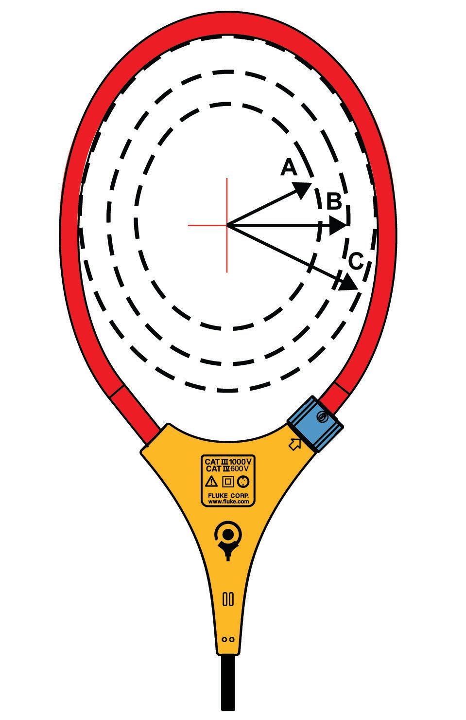 |
|||
| Distance from Optimum | i2500-10 Flex | i2500-18 Flex | Error |
| A | 0.5 in (12.7 mm) | 1.4 in (35.6 mm) | ±0.5 % |
| B | 0.8 in (20.3 mm) | 2.0 in (50.8 mm) | ±1.0 % |
| C | 1.4 in (35.6 mm) | 2.5 in (63.5 mm) | ±2.0 % |
| Measurement uncertainty assumes centralized primary conductor at optimum position, no external electrical or magnetic field, and within operating temperature range. | |||
| DC Current | |||
| Range | 999.9 A | ||
| Resolution | 0.1 A | ||
| Accuracy | 2 % RD + 5 digits[1] | ||
| [1] When using the ZERO (B) function to compensate for offsets. | |||
| AC Voltage | |||
| Range | 600.0 V | ||
| 1000 V | |||
| Resolution | 0.1 V (≤600.0 V) | ||
| 1 V (≤1000 V) | |||
| Accuracy | 1 % RD + 5 digits (20 Hz to 500 Hz) | ||
| DC Voltage | |||
| Range | 600.0 V | ||
| 1500 V | |||
| Resolution | 0.1 V (≤600.0 V) | ||
| 1 V (≤1500 V) | |||
| Accuracy | 1 % RD + 5 digits | ||
| mV dc | |||
| Range | 500.0 mV | ||
| Resolution | 0.1 mV | ||
| Accuracy | 1 % RD + 5 digits | ||
| Amps Frequency: Jaw | |||
| Range | 5.0 Hz to 500.0 Hz | ||
| Resolution | 0.1 Hz | ||
| Accuracy | 0.5 % RD + 5 digits | ||
| Trigger Level | 5 Hz to 10 Hz, ≥10 A | ||
| 10 Hz to 100 Hz, ≥5 A | |||
| 100 Hz to 500 Hz, ≥10 A | |||
| Amps Frequency: Flexible Current Probe | |||
| Range | 5.0 Hz to 500.0 Hz | ||
| Resolution | 0.1 Hz | ||
| Accuracy | 0.5 % RD + 5 digits | ||
| Trigger Level | 5 Hz to 20 Hz, ≥25 A | ||
| 20 Hz to 100 Hz, ≥20 A | |||
| 100 Hz to 500 Hz, ≥25 A | |||
| Voltage Frequency | |||
| Range | 5.0 Hz to 500.0 Hz | ||
| Resolution | 0.1 Hz | ||
| Accuracy | 0.5 % RD + 5 digits | ||
| Trigger Level | 5 Hz to 20 Hz, ≥5 V | ||
| 20 Hz to 100 Hz, ≥5 V | |||
| 100 Hz to 500 Hz, ≥10 V | |||
| DC Power | |||
| Range | 600.0 kVA (600.0 V dc range) | ||
| 1500 kVA (1500 V dc range) | |||
| Resolution | 0.1 kVA | ||
| 1 kVA | |||
| Accuracy | 2 % RD + 2.0 kVA | ||
| 2 % RD + 20 kVA | |||
| Resistance | |||
| Range | 600.0 Ω | ||
| 6000 Ω | |||
| 60.00 kΩ | |||
| Resolution | 0.1 Ω (≤600.0 Ω) | ||
| 1 Ω (≤6000 Ω) | |||
| 0.01 kΩ (≤60.00 kΩ) | |||
| Accuracy | 1 % RD + 5 digits | ||
| Capacitance | |||
| Range | 100.0 μF | ||
| 1000 μF | |||
| Resolution | 0.1 μF (≤100.0 μF) | ||
| 1 μF (≤1000 μF) | |||
| Accuracy | 1 % RD + 5 digits | ||
| Inrush Trigger Level | 5 A | ||
| Mechanical | |||
| Size (L x W x H) | 281 mm x 84 mm x 49 mm | ||
| Weight (with batteries) | 520 g | ||
| Jaw Opening | 34 mm | ||
| Flexible Current Probe Diameter | 7.5 mm | ||
| Flexible Current Probe Cable Length | |||
| (head to electronics connector) | 1.8 m | ||
| Environmental | |||
| Operating Temperature | -10 °C to 50 °C | ||
| Storage Temperature | -40 °C to 60 °C | ||
| Operating Humidity | Non condensing (<10°C) | ||
| ≤90 % RH (at 10 °C to 30 °C) | |||
| ≤75 % RH (at 30 °C to 40 °C) | |||
| ≤45 % RH (at 40 °C to 50 °C) | |||
| Operating Altitude | 2000 m | ||
| Storage Altitude | 12 000 m | ||
| Ingress Protection (IP) Rating | IEC 60529: IP54 non-operating | ||
| Electromagnetic Compatibility (EMC) | |||
| International | IEC 61326-1: Portable, Electromagnetic Environment, IEC 61326-2-2 CISPR 11: Group 1, Class A | ||
| Group 1: Equipment has intentionally generated and/or uses conductively-coupled radio frequency energy that is necessary for the internal function of the equipment itself. | |||
| Class A: Equipment is suitable for use in all establishments other than domestic and those directly connected to a low-voltage power supply network that supplies buildings used for domestic purposes. There may be potential difficulties in ensuring electromagnetic compatibility in other environments due to conducted and radiated disturbances. | |||
| Caution: This equipment is not intended for use in residential environments and may not provide adequate protection to radio reception in such environments. | |||
| Korea (KCC) | Class A equipment (Industrial Broadcast & Communications Equipment) | ||
| Class A: Equipment meets requirements for industrial electromagnetic wave equipment and the seller or user should take notice of it. This equipment is intended for use in business environments and not to be used in homes. | |||
| USA (FCC) | 47 CFR 15 subpart B. This product is considered an exempt device per clause 15.103. | ||
| Safety | |||
| General | IEC 61010-1, Pollution Degree 2 | ||
| Measurement | IEC 61010-2-032: CAT III 1500 V / CAT IV 600 V | ||
| IEC 61010-2-033: CAT III 1500 V / CAT IV 600 V | |||
| Wireless Radio | |||
| Radio frequency certification | FCC ID: T68-FBLE, IC: 6627A-FBLE | ||
| Wireless Radio Frequency Range | 2400 MHz to 2483.5 MHz | ||
| Output Power | <100 mW | ||
| SIMPLIFIED EU DECLARATION OF CONFORMITY | |||
| Hereby, Fluke declares that the radio equipment contained in this Product is in compliance with Directive 2014/53/EU. | |||
| The full text of the EU declaration is available at the following Internet address: | |||
| www.fluke.com/en-us/declaration-of-conformity | |||
| Specifications | ||
| Voltage DC | Maximum voltage | 1000 V |
| Accuracy | ±(0.05% + 1) | |
| Maximum resolution | 10 µV | |
| Voltage AC | Maximum voltage | 1000 V |
| Accuracy | ±(0.7% + 2) True RMS | |
| AC bandwidth | 20 kHz with low pass filter; 3 dB @ 1 kHz | |
| Maximum resolution | 0.1 mV | |
| Current DC | Maximum amps | 10 A (20 A for 30 seconds maximum) |
| Amps accuracy | ±(0.2% + 2) | |
| Maximum resolution | 0.01 µA | |
| Current AC | Maximum amps | 10 A (20 A for 30 seconds maximum) |
| Amps accuracy | ±(1.0% + 2) True RMS | |
| Maximum resolution | 0.1 µA | |
| Resistance | Maximum resistance | 50 MΩ |
| Accuracy | ±(0.2% + 1) | |
| Maximum resolution | 0.1 Ω | |
| Capacitance | Maximum capacitance | 9,999 µF |
| accuracy | ±(1% + 2) | |
| Maximum resolution | 0.01 nF | |
| Frequency | Maximum frequency | 200 kHz |
| Accuracy | ±(0.005% + 1) | |
| Maximum resolution | 0.01 Hz | |
| Duty cycle | Maximum duty cycle | 99.9% |
| Accuracy | ±(0.2% per kHz + 0.1%) | |
| Maximum resolution | 0.1% | |
| Temperature measurement | –200.0 °C – 1090 °C –328.0 °F – 1994.0 °F excluding probe |
|
| 80 BK temperature probe | –40.0 °C – 260 °C –40.0 °F – 500 °F, 2.2 °C or 2% whichever is greater |
|
| Conductance | Maximum conductance | 60.00 nS |
| Accuracy | ±(1.0% + 10) | |
| Maximum resolution | 0.01 nS | |
| Diode | Range | 3 V |
| Resolution | 1 mV | |
| Accuracy | ±(2% + 1) | |
| Duty cycle range | Accuracy | Within ±(0.2% per kHz + 0.1%) |
| Environmental Specifications | ||
| Operating temperature | –20 °C to + 55 °C | |
| Storage temperature | –40 °C to + 60 °C | |
| Humidity (without condensation) | 0% – 90% (0 °C – 35 °C) 0% – 70% (35 °C – 55 °C) |
|
| Operating Altitude | 2000 m | |
| Safety Specifications | ||
| Overvoltage category | EN 61010–1 to 1000 V CAT III, 600V CAT IV | |
| Agency approvals | CE, CSA, RCM | |
| Mechanical and General Specifications | ||
| Size | 201 x 98 x 52 mm (with holster) | |
| Weight | 355 g 624 g – with holster |
|
| Display | Digital | 6000 counts updates 4/sec. 19,999 counts in high–resolution mode |
| Analog | 32 segments, updates 40/sec | |
| Frequency | 19,999 counts, updates 3/sec at > 10 Hz | |
| Warranty | Lifetime | |
| Battery Life | Alkaline | ~400 hours typical, without backlight |
| Shock | 1 Meter drop per IEC 61010–1:2001 | |
| Vibration | Per MIL–PRF–28800 for a Class 2 instrument | |
Manuals + Resources: PVA-1500HE2 I-V Curve Tracer, Insulation, Clamp and Multimeter Kit
- PVA-1500HE2/PVA-1500T2/ SolSensor-300V3 User Manual | Users manual
- PVA-1500HE2/PVA-1500T2/ SolSensor-300V3 | Safety sheet
- PVA-1500HE2/PVA-1500T2/ SolSensor-300V3 | Product specification
- PVA-1500HE2/PVA-1500T2/ SolSensor-300V3 |
- PVA-1500HE2/PVA-1500T2/ SolSensor-300V3 | Getting started
- Radio Frequency Data Class A | Instruction sheet