Every Fluke clamp meter offers a different combination of functions, but no matter which one you grab, you’ll need to know what the symbols and buttons mean as well as where they show up on the display screen. Below are composite images of clamp meters’ display, dial, and the buttons. The diagrams aren’t specific to one clamp meter model, they illustrate the range of functions that can be found on multiple clamp meters. No single Fluke model contains all of the functions listed below.
Clamp meter display symbols
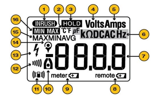
| 1 | Inrush is active |
| 2 | Temperature |
| 3 | Hold is active |
| 4 | Volts |
| 5 | Amps |
| 6 | Capacitance, measured in farads and microfarads (F or µF); resistance, measured in ohms and kilo-ohms (Ω and kΩ); direct current (DC); alternating current (AC); frequency (Hz) |
| 7 | Digits (measurement readout) |
| 8 | Low-battery indicator for remote display (Fluke 381 only) |
| 9 | Low-battery indicator for meter |
| 10 | Measurement being taken by the clamp's jaw |
| 11 | RF signal is being sent to remote display (Fluke 381 only) |
| 12 | Continuity |
| 13 | Hazardous voltage is present |
| 14 | Measurement being taken by a flexible current probe |
| 15 | Minimum, maximum or average reading is shown |
| 16 | Min/Max is active |
Clamp meter symbols diagram
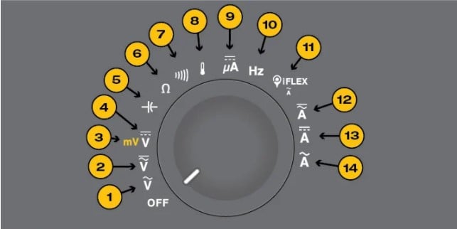
| 1 | AC (alternating current) volts |
| 2 | AC and DC (direct current) volts |
| 3 | Millivolts |
| 4 | Millivolts |
| 5 | Capacitance |
| 6 | Resistance |
| 7 | Continuity |
| 8 | Temperature |
| 9 | DC microamps |
| 10 | Frequency |
| 11 | AC amps measured by a Rogowski (iFlex®) coil |
| 12 | AC and DC amps |
| 13 | DC amps |
| 14 | AC amps |
Clamp meter buttons diagram
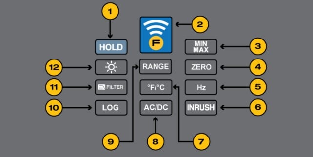
| 1 | Hold: Freezes the display reading. Reading is released when button is pushed a second time. |
| 2 | Fluke Connect™ radio: Activates the radio and starts the wireless module discovery procedure; Wireless icon shows in the display when the radio is on. Deactivates the radio when the measuring procedure is finished. |
| 3 | Min Max: On first push, display shows maximum input. On subsequent pushes, minimum and average inputs are shown. Works in current, voltage and frequency modes. |
| 4 | Zero: Removes DC offset from DC current measurements. This button sometimes appears in yellow and doubles as the shift button, corresponding to yellow functions scattered around the dial. |
| 5 | Hz: Frequency. |
| 6 | Inrush: Measures inrush current by taking approximately 400 samples over a 100-millisecond period and calculating the starting current envelope. |
| 7 | °F/°C: Temperature, in Fahrenheit or Celsius. |
| 8 | AC/DC: On selected models, permits user to toggle between ac and dc measurements. |
| 9 | Range: Allows the user to switch from auto range to manual range. |
| 10 | Log: Initiates data recording process. |
| 11 | Low pass filter: Aims to eliminate electronic interference that might distort readings. |
| 12 | The beaming orb: On/off switch for display backlight. |
Note:
On some models, a few function icons are displayed in yellow. This indicates the meter’s yellow function button must be pressed to select those measurements.